
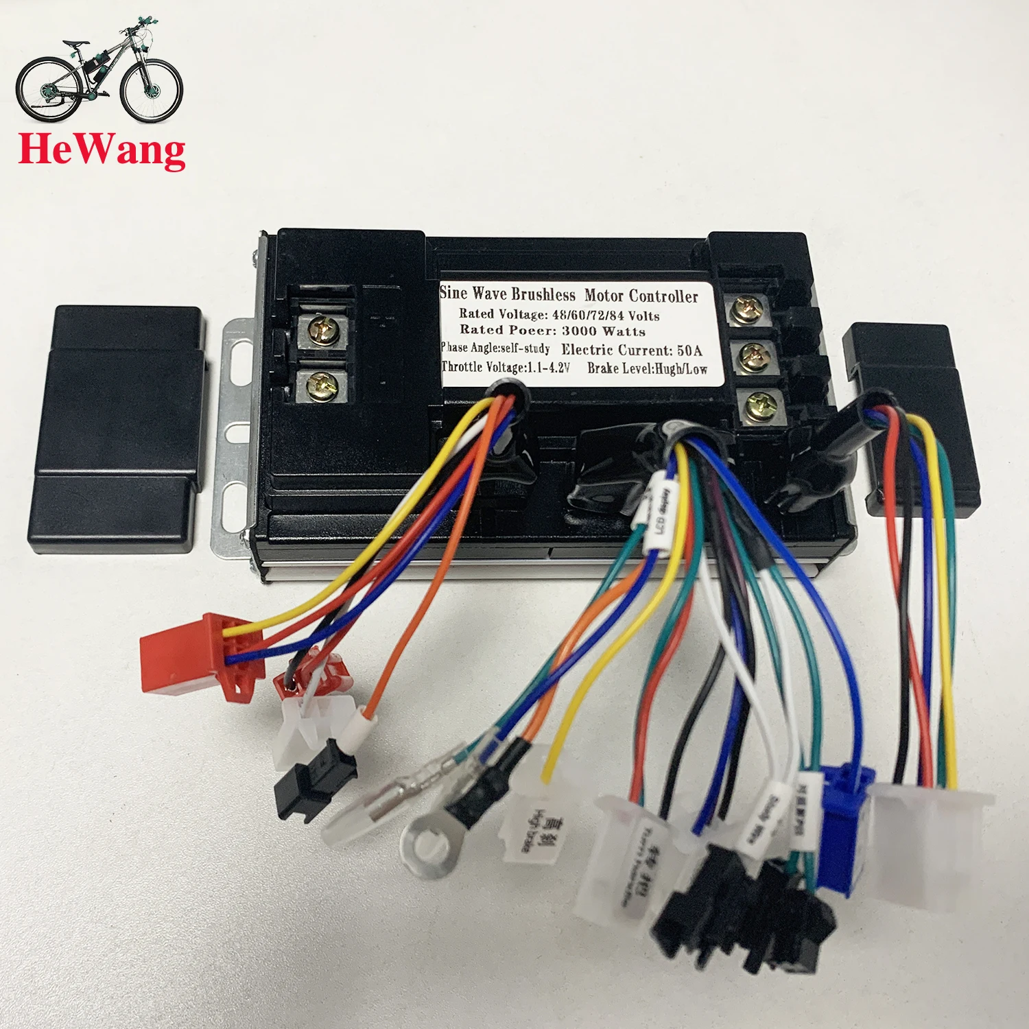
three mode sine wave controller 48V 52V 60V 72V 1500W 2000W 2500W 3000W e-bike brushless moter dc controller 50A for E-scooter


three mode sine wave controller 48V 52V 60V 72V 1500W 2000W 2500W 3000W e-bike brushless moter dc controller 50A for E-scooter
SPECIFICATIONS
2000W Sine wave controller: 1500W Sine wave controller
3000W Sine wave controller: 2500W Sine wave controller
36v Controller: 72v 2000w
40A 50A: Brushless Motor Controller
45A Controller: 72V 3000W
48v Controller,: 84V 2000W
52v Controller: 60v 2000w
60v Controller: 48v 2000w
72v Controller: Controller 84v
Brand Name: NONE
Choice: yes
Electric Scooters: Sine wave controller
High-concerned chemical: None
Model Number: 3000W
Origin: Mainland China
Voltage: 48V
is_customized: Yes
36/48/52/64/72/84V Sine Wave 50A 500w 1500W 2000W 3000W Three Mode Brushless Module Controller for Electric Bicycle E-Scooter motorcycle
Material: aluminum alloy
Working voltage: 36V 48V 52V 60V 64V 72V 84V
Rated power: 500-1500-2000-3000w
Current: 50A
Size: 18CM*9.5CM*5CM
MOS tube: SKST049N08
Function: three-speed shift, three-speed button, anti-theft alarm, smart cruise, LCD instrument, pointer instrument, high battery brake, low battery brake, P gear selection
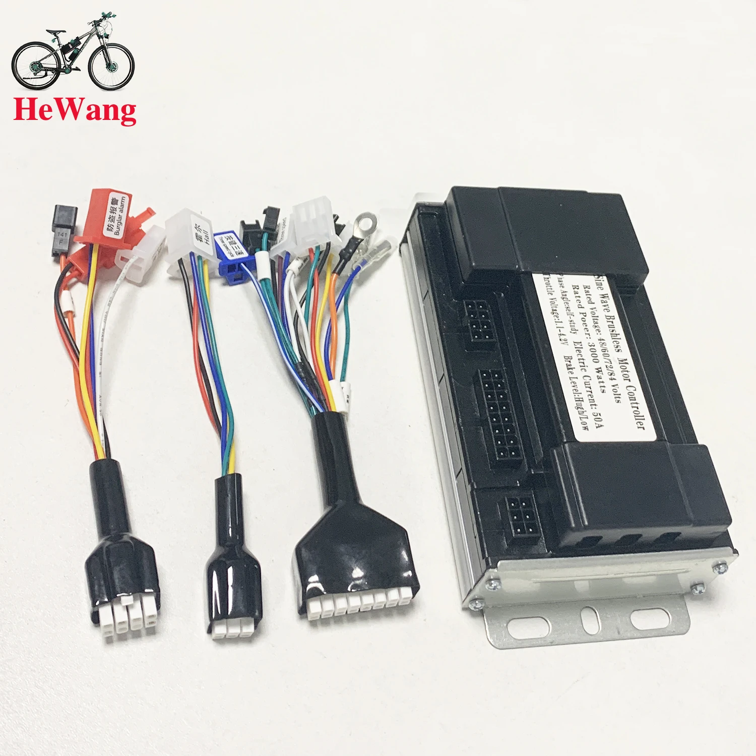
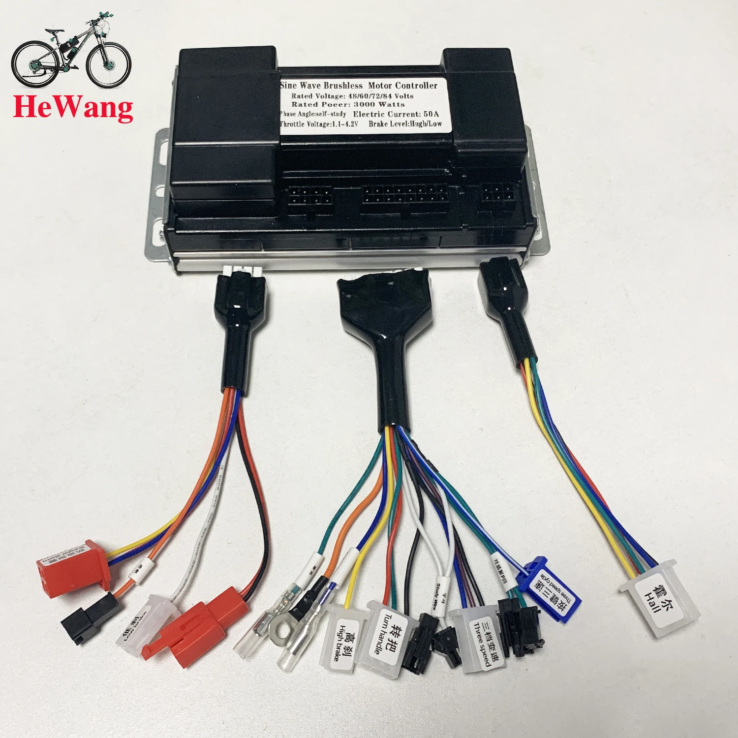 How to connect ?
1. connect the battery
2. connect the controller throttle line(color to color),connect electric lock
(if your throttle not have key lock,controller key lock can be shorted)
3. connect the hall line(if motor without hall line, don't need connect)
4.docking the two intelligent recognition lines, the wheel will forward or reverse.
(11.if wheel forward ,Separate the intelligent recognition line.
2.1 if wheel reverse, Separate the intelligent recognition line. Docking the intelligent recognition line again,if wheel forward ,Separate the self-learning line.)
5.other functions can be connected as needed.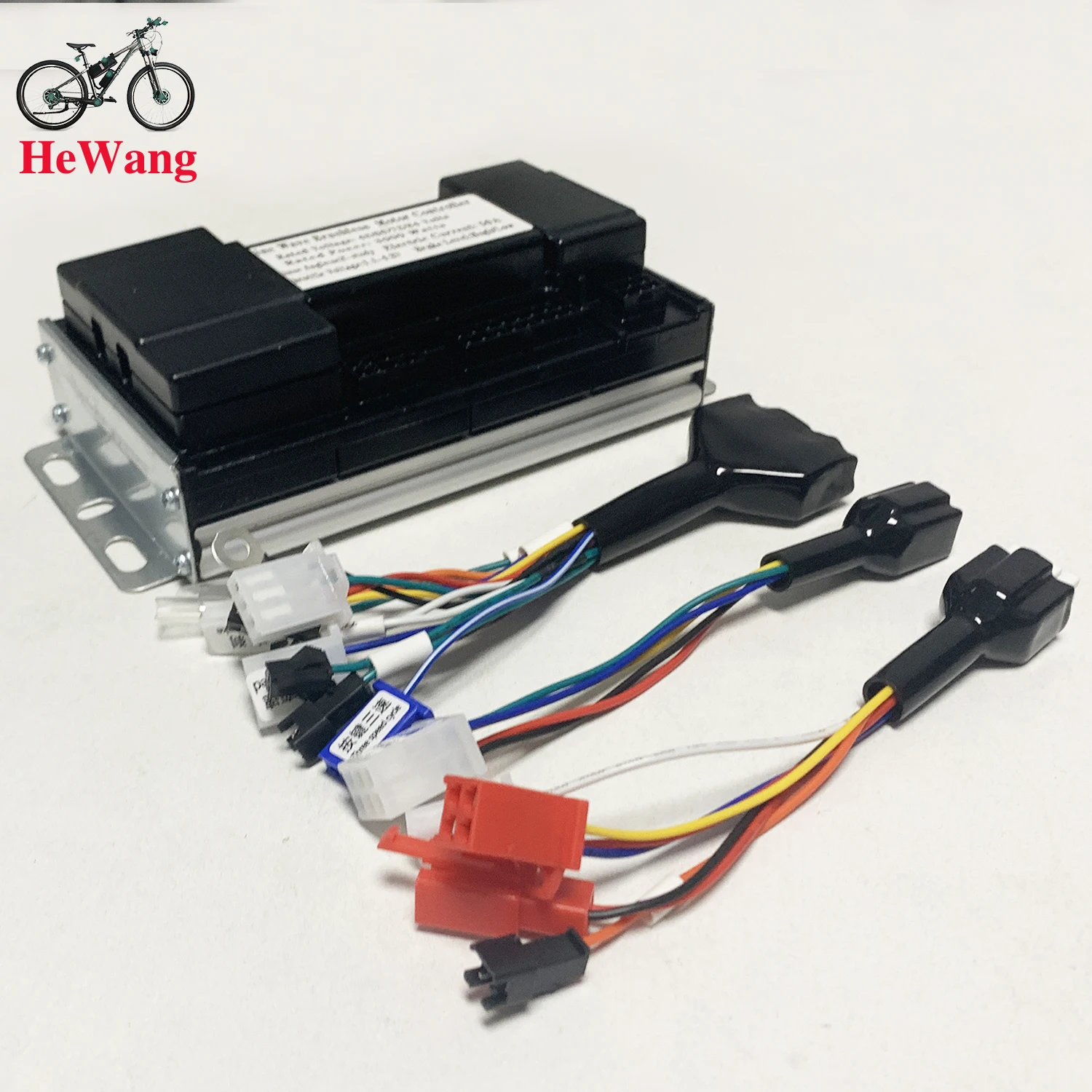
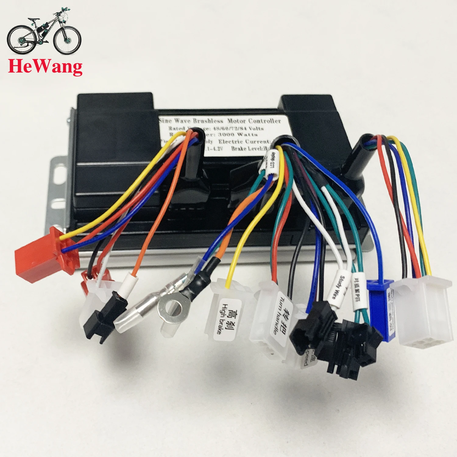
 1.Burglar alarm 2.cruise 3.Low brake
4.防盗电源 Anti-theft power supply
5.指针仪表线 Pointer instrument line
6. 电源线 power cord 7. LCD dispaly
8. Hight brake 9. Turn handle 10. study wire
11. Three speed 12. 对插接p档
P-file for plugging 13.three speed cycle
14.Hall 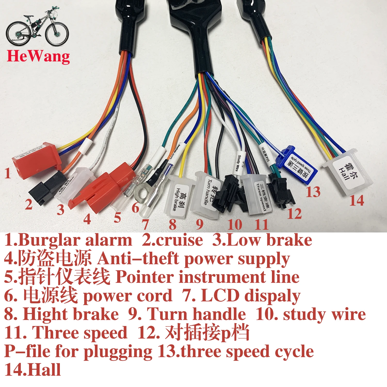
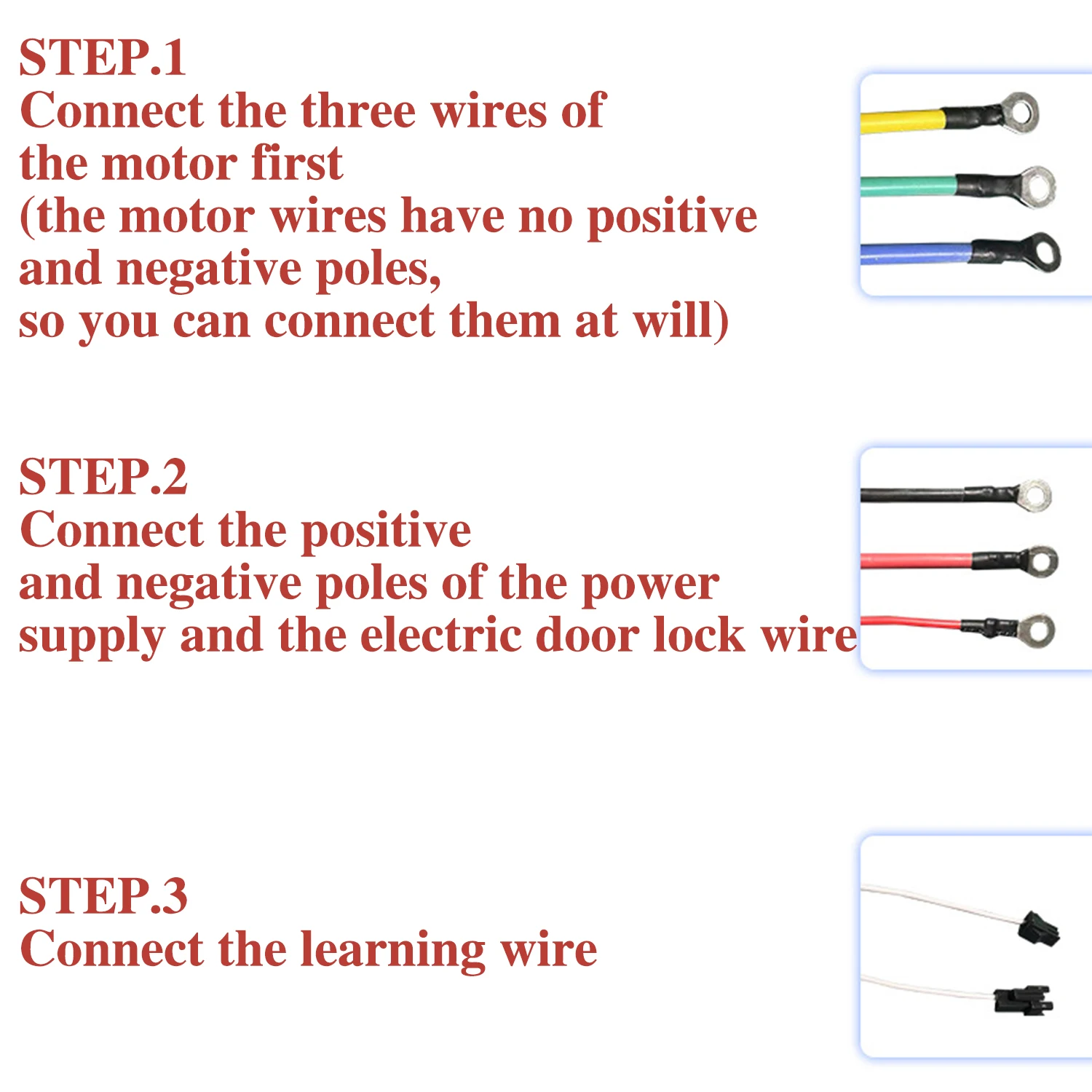
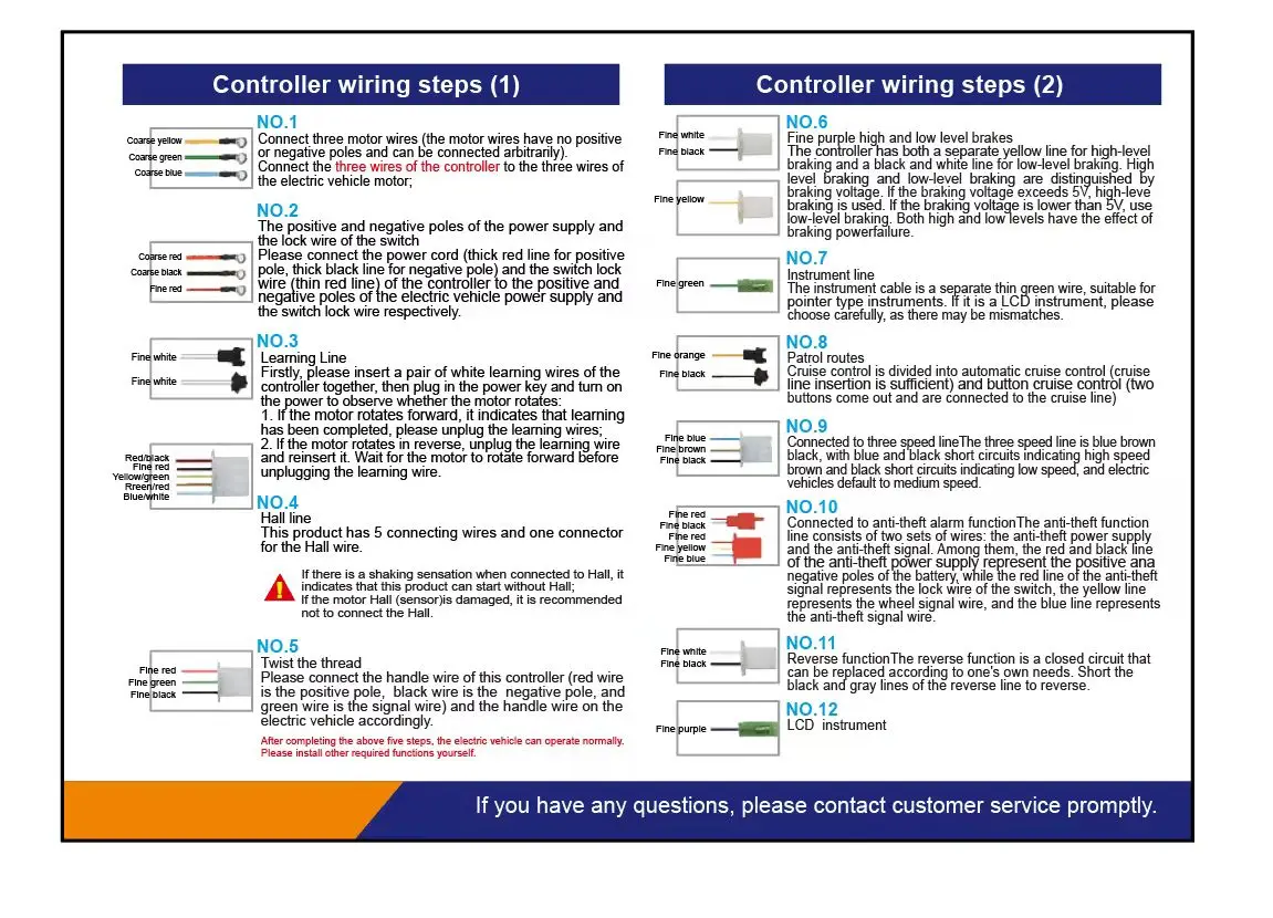
 STEP.1 Connect the three wires of the motor first (the motor wires have no positive and negative poles, so you can connect them at will)
Connect the three thick yellow, green and blue wires of the motor with the three motor wires of the electric car, and use the rear wheel to feel if there is any resistance. If there is no resistance, continue to the second step. If there is resistance, check if the three wires of the motor are not connected properly. (How to detect whether the motor is good or bad: touch the motor wires of the car in pairs. If there is resistance, it means the motor is good. If there is no force, it means the motor has a problem).
STEP.2 Connect the positive and negative poles of the power supply and the electric door lock wire
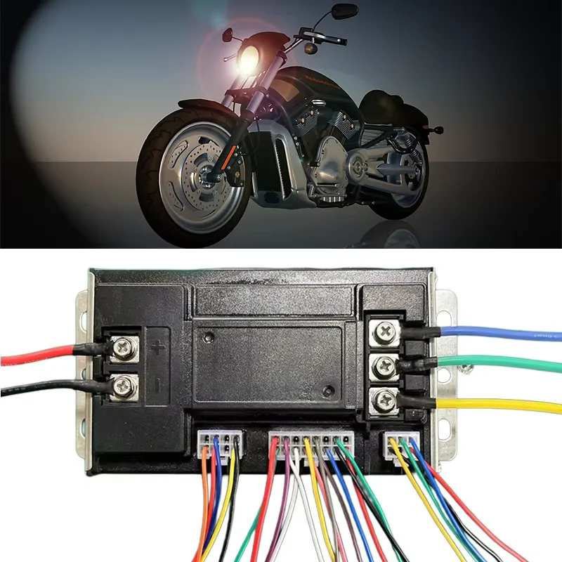
The power wire of the controller, the thick red is the positive pole, the thick black is the negative pole, and the thin red wire is the electric door lock wire, which can be matched with the positive and negative poles of the power supply and the electric door lock wire of your electric vehicle! (Note that the positive and negative poles of the power supply must not be connected in reverse, otherwise the controller will be burned. If the electric vehicle does not have an electric door lock wire, the electric door lock wire on the controller and the positive pole of the power supply can be short-circuited together)
STEP.3 Connect the learning wire
There is a pair of white learning wires on the controller. Plug the learning wires together, then plug in the power key, turn on the power, and see if the motor rotates automatically. If it rotates forward, just unplug the learning wire directly. If it rotates reversely, unplug the learning wire and re-plug it to rotate forward, and then unplug the learning wire to complete the learning (after this step is completed, the motor automatically rotates to prove that the controller is good, and if it does not rotate, it proves that there is a problem with the controller)
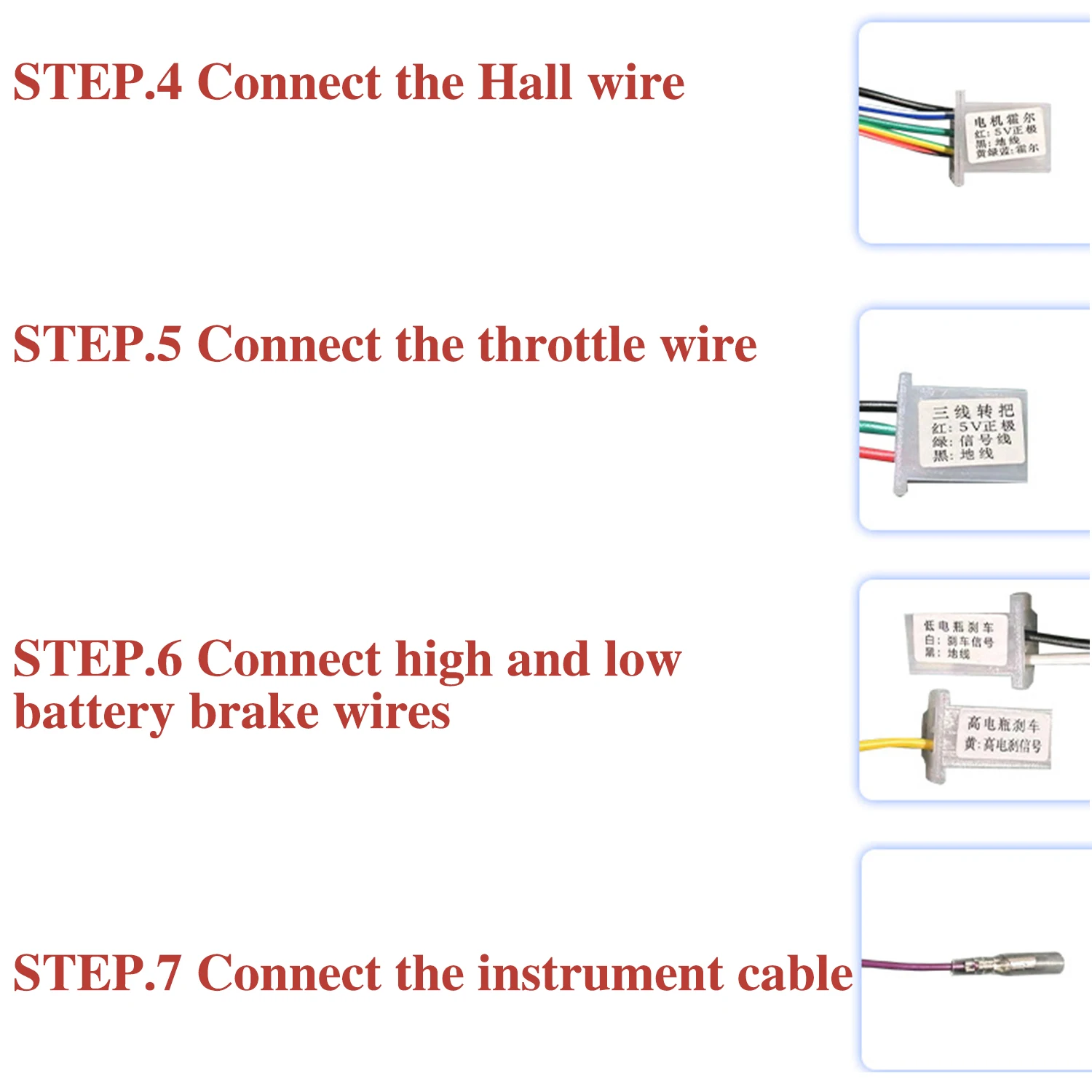
 STEP.4 Connect the Hall wire
Plug in the Hall wire, which has 5 wires with one head. Note: The Hall wire has positive and negative poles. The positive pole of the Hall wire of our controller is red, and the negative pole is black. As long as the positive and negative poles are correct, it doesn't matter if the other 3 wires have different colors. Our controller is a brushless controller, which can be used with or without Hall wires. However, if the Hall wire of the electric vehicle motor is broken, the following situations will occur: 1. The vehicle will shake and be weak when starting, but it will be fine when riding; 2. The anti-theft alarm can be used, but the motor lock function cannot be used; 3. The high gear of the three-speed cannot be used, but the low gear can be used
STEP.5 Connect the throttle wire
Find the throttle wire for control, red, green and black, red is the positive pole of the throttle, black is the negative pole of the throttle, green is the signal wire of the throttle, then find the throttle wire on the electric vehicle, note that the throttle wire of the electric vehicle must come out from the throttle. If necessary, you can disassemble the throttle to identify which one is the throttle connector in the electric vehicle, connect the throttle connector, turn the throttle, and see if the motor rotates. If there is no response when turning the throttle at this time:
1. The positive and negative poles of the throttle are not connected correctly;
2. The throttle is broken, just change a throttle. (Friends with a multimeter can use the multimeter to test the throttle signal wire to see if there is a voltage output. Set the multimeter to the voltage output state, connect the red needle to the green signal wire of the throttle, and connect the black needle to the black ground wire of the throttle to see if there is a 0-5V voltage. If there is no voltage, it proves that the throttle is broken. Be sure to connect the controller and the throttle and turn on the power to test, otherwise it will not work).
STEP.6 Connect high and low battery brake wires
1. The controller has both a single yellow high battery brake wire and a white and black low battery brake wire. High battery brakes and low battery brakes are distinguished by brake voltage. If the brake voltage is higher than 5V, use the high battery brake, and if the brake voltage is lower than 5V, use the low battery brake. The effect of high battery and low battery brakes is to cut off the power of the brake. First, identify how many wires come out of your brake handle, one for the high battery brake and two for the low battery brake. (If your car is a turn brake, you need to pull out the white and black low battery brake and put it together with the turn handle wire to achieve the effect of cutting off the power of the brake). 2. Because EABS electronic brakes are built into the controller program, the electronic brake effect will be generated as long as the brake power is cut off. The electronic brake is when the brake power is cut off. The motor generates a reverse force to brake. Sometimes there will be a "click" sound, which has no effect on the motor. Please feel free to use it.
STEP.7 Connect the instrument cable
The instrument cable is a single thin green cable, suitable for pointer instruments. If it is an LCD instrument, please choose carefully, as there may be mismatches.
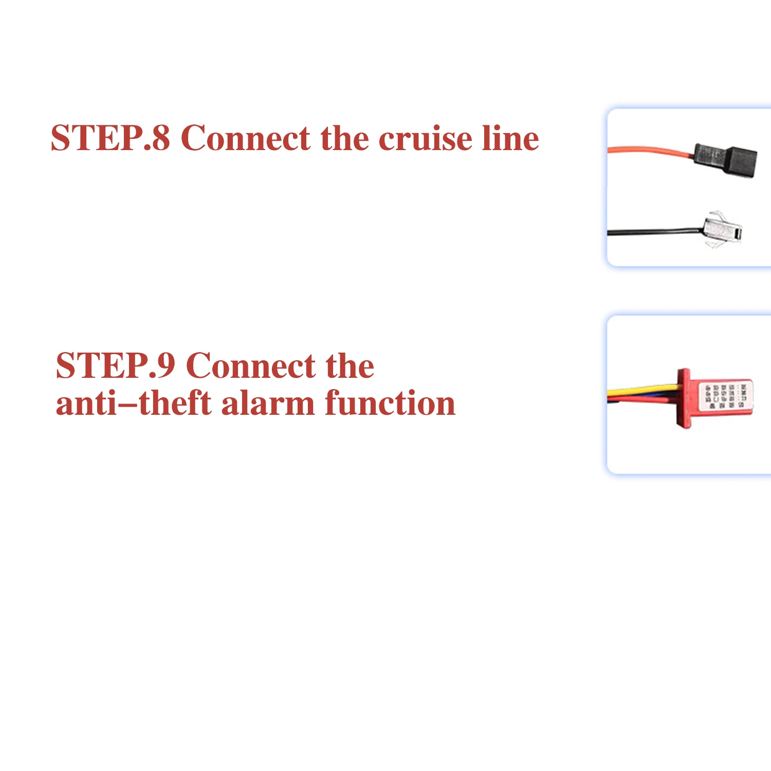
STEP.8 Connect the cruise line
Cruise can be divided into automatic cruise (just plug the cruise line) and button cruise (just connect the two lines from the button to the cruise line).
STEP.9 Connect the anti-theft alarm function
The anti-theft function line consists of two groups of lines: the anti-theft power supply and the anti-theft signal. Among them, the red and black lines of the anti-theft power supply represent the positive and negative poles of the battery respectively, while the red line of the anti-theft signal is the electric door lock line, the yellow line is the wheel signal line, and the blue line is the anti-theft signal line. Be careful not to connect the different types of lines incorrectly!
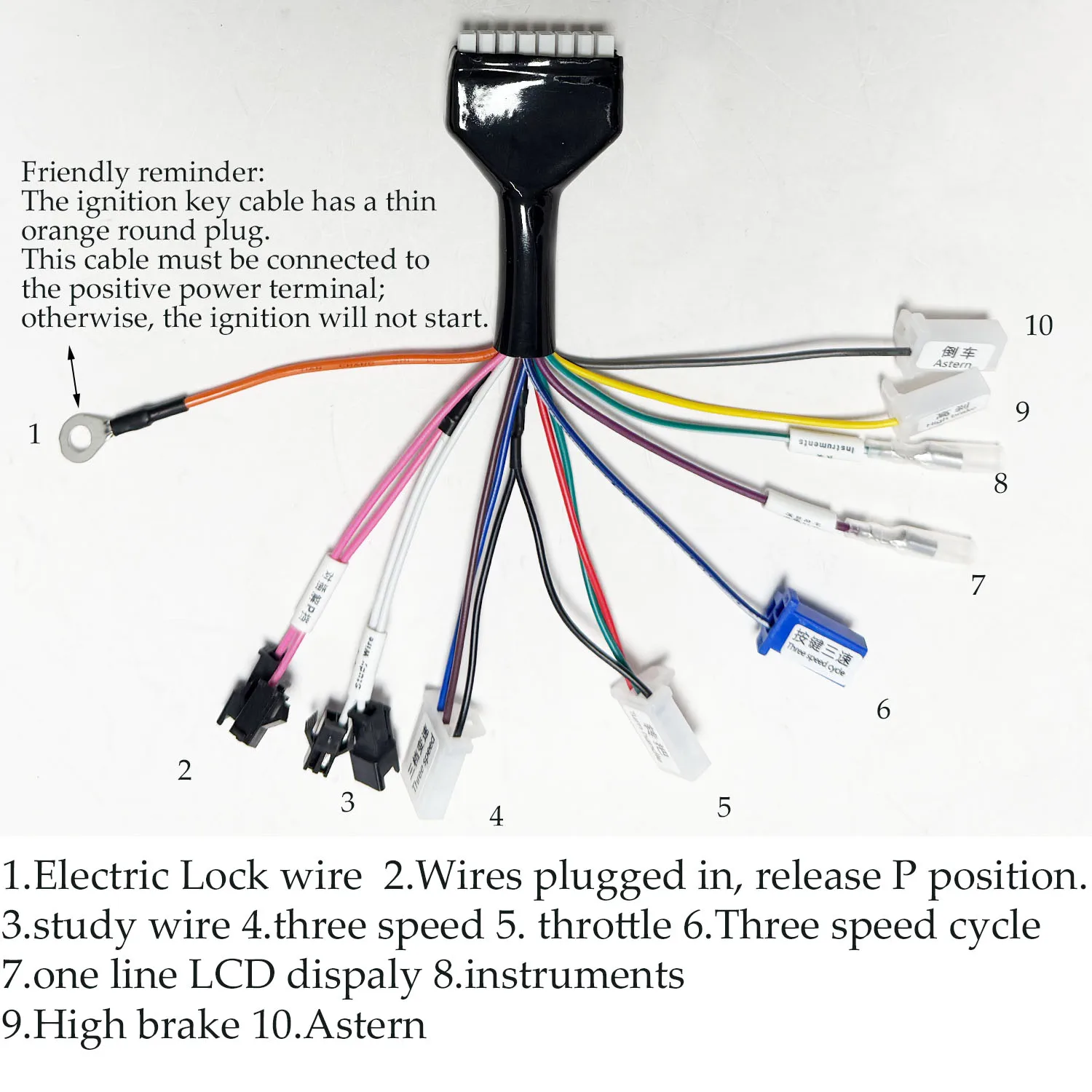 Friendly reminder The ignition key cable has a thin orange round plug.This cable must be connected to the positive power terminalotherwise, the ignition will not start.
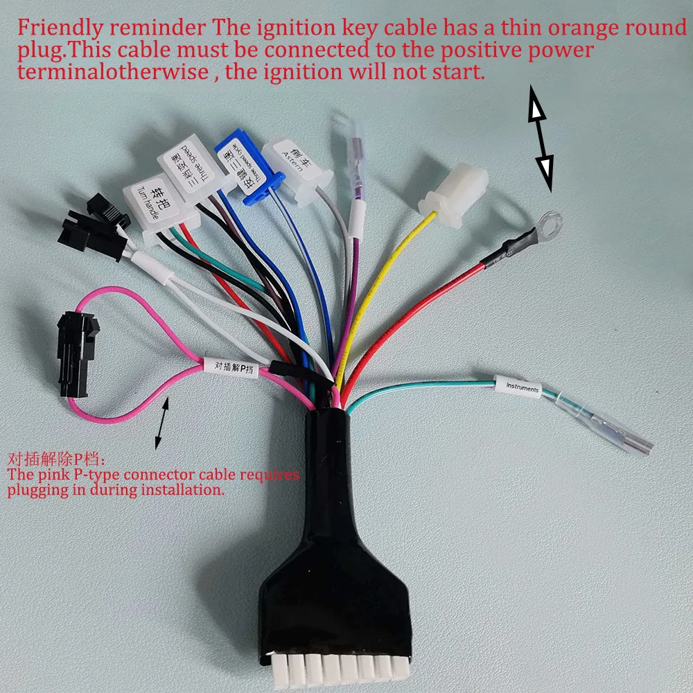 对插解除P档:The pink P-type connector cable requires plugging in during installation.
